OK, Further testing....
Start with Pressure Regulator via Resistor > Flow Meter > upper Pressure Take-off (uPTO) > 4mm Calibrator > Air.
Flow 20L gives 74mm at upper PTO.
Add 35mm extension of 13.3mm tubing, flow unchanged, 20 & 67.5mm
Remove, 20 & 74
On again, 20 & 68
Off again, 20 & 74.5
(The Flowmeter has some space above the top marking at 20L/Min, so I'm in no danger of "overload". I'm not stopping the flow in these tests. But I am monitoring it.)
Now add 130mm of 13.3mm tubing (more than 8 times diameter plus some spare to push on to the Calibrator tail and onto a T junction. 20 & 65
Plug in the T junction with lower PTO, but that side tube crimped. Lower end of T open to air. 20 & 66
Now read pressure to atmosphere at lower PTO, 20 & 0
Now switch to Diff Mode, and measure between the PTOs. 20 & 65.5
Blowing machine
-
Terry McGee

- Posts: 3335
- Joined: Sun Dec 12, 2004 4:12 pm
- Please enter the next number in sequence: 1
- Location: Malua Bay, on the NSW Nature Coast
- Contact:
-
david_h
- Posts: 1735
- Joined: Mon Aug 13, 2007 2:04 am
- Please enter the next number in sequence: 1
- Location: Mercia
Re: Blowing machine
Hmm. If that was all without touching the regulator it is baffling. It looks like what is going on beyond a windway exit can change the resistance - and not in the direction we would expect. Clutching at straws but is the is the calibrator lying on the bench or held up in the air? Anything that could be baffling it with no tube on?
The regulator and resistance are part of the system. If thinking 'what would we expect to happen when changing the resistance with the system running" some of what happens is across the regulator and between the regulator and the air under the ball in the flow meter.
What happens to the flow meter if after putting the short tube on the pressure at the manometer is adjusted back to what is was before? Does the flow go up enough to notice?
Not really related at the moment but I keep reminding myself that most of the velocity change and pressure drop is occurring at the boring end of the windway, it's entrance. The pressure inside the exit is nearly atmospheric. Reading that page Tunborough linked above (https://neutrium.net/fluid-flow/pressur ... -and-exits) I wonder if those differences in the moulding of the Feadog Mk1 windway entrance may make a difference. Also (sorry to keep coming back to it) if we form an embouchure with our lips much of the pressure drop is in our lips. Even without deliberate shaping the contribution to resistance at the windway entrance may depend on how a player places their lips.
Edit to add. To give us an idea of the 'scale' of things - what happens if a finger is gently moved towards the calibrator exit?
Last edited by david_h on Wed Mar 15, 2023 10:43 am, edited 1 time in total.
Re: Blowing machine
trill asks MEMS flowmeter mfr:Terry McGee wrote: ↑Mon Mar 13, 2023 7:16 pm . . . It's certainly offering greater accuracy and resolution at STP. But it would be a bitter blow to pay all that money and find out then that it's highly susceptible to pressure.
". . . if the pressure of the flow we want to measure varies from 1.0atm to 1.05atm, will that affect the reading ? . . . Stated another way, are the flowmeters sensitive to pressure ?"
mfr replies:
"The meter is a mass flow meter, i.e. the measurement will not change with pressure or temperature variations."
Interim update: this is turning into a lesson in how the MEMS sensors, as a class, operate, especially their error characteristics.
Note: that "1.05atm" is the pressure a player uses (plus margin) to hit the 3rd D (D7) on old Gen.
A player blowing a whistle is blowing "just above" ambient atmospheric.
More later.
(trill quietly ponders ramifications . . . hmmm . . . mass is conserved across our whistle-head/orifice . . . )
-
david_h
- Posts: 1735
- Joined: Mon Aug 13, 2007 2:04 am
- Please enter the next number in sequence: 1
- Location: Mercia
Re: Blowing machine
Yes, and energy**. That's how Bernoulli's equation is derived. By using Bernoulli's equation we (and much of industry much of the time) are assuming volume is also conserved (that air is incompressible). We know it isn't. I don't think that matters - other than for the flow meter.
@Terry. If you read my last post yesterday - I just added a line.
** edit to add. Not across the whistle-head/orifice, but within the overall system - it is lost by the things that contribute to Tunbourough's K
Last edited by david_h on Thu Mar 16, 2023 2:55 am, edited 1 time in total.
-
Tunborough
- Posts: 1419
- Joined: Sun Dec 05, 2010 2:59 pm
- antispam: No
- Please enter the next number in sequence: 10
- Location: Southwestern Ontario
Re: Blowing machine
As baffling as it seems, the pressure across the calibrator is clearly less when there is some tubing below the calibrator. This suggests that when you measured with the flowmeter below the calibrator it wasn't that the flowmeter discharged to open air, but that there was something below the calibrator. To take a closer look at this, I'd appreciate it if you could measure the pressures for flowmeter -> pressure takeoff -> calibrator -> 130 mm tubing -> open air on a couple more calibrators, perhaps the three tapered calibrators, at 5, 10, 15, and 20 L/min. Then I'd like to try a similar test on the Feadog Mk 1 and the old Generation whistle heads with and without the whistle tube plugged into the whistle head, again at 5, 10, 15, 20 L/min.
-
Tunborough
- Posts: 1419
- Joined: Sun Dec 05, 2010 2:59 pm
- antispam: No
- Please enter the next number in sequence: 10
- Location: Southwestern Ontario
Re: Blowing machine
It is a bit unexpected, but the measurements we have so far imply little or no energy loss at the entrance to the windway. The shape of the mouth and the lips will affect the pressure and speed within the mouth, but it isn't clear yet how much it will affect what happens in the windway and below.
-
Terry McGee
- Posts: 3335
- Joined: Sun Dec 12, 2004 4:12 pm
- Please enter the next number in sequence: 1
- Location: Malua Bay, on the NSW Nature Coast
- Contact:
Re: Blowing machine
Sorry for the slow response, had the band here this morning to prepare for our St Paddy's Day gig in the tiny township of Mogo tomorrow. You'll love the name of the place we're playing at. "Grumpy & Sweetheart's". No, I don't know the backstory either!
To do this I cut another 40mm piece of 13.3mm tubing, but in this one, I tapped a hole 5mm in from the Calibrator end and screwed in a PTO spigot. So when I push it on to the Calibrator the spigot will commune with the air around the output of the Calibrator. I'll call it "LPTO + 35mm tube".
So start with the end of the Calibrator open to air....
20L gives 73.5 at the upper PTO
Add the LPTO + 35mm tube, upper PTO drops to 66.5mm
Plug Upper PTO and measure at LPTO, -8mm
Diff mode between UPTO and LPTO, 73.5mm
So the Calibrator still has circa 73.5mm pressure across it, but when plugged into the 35mm extension, a partial vacuum forms at the Calibrator output, "sucking down" the UPTO pressure? 66.5 plus 8 being close to 73.5. Differential mode measurement between the PTOs takes that into account. Plausible interpretation?
All of this suggests to me that trying to measure downstream from the Window or Calibrator is just adding to our confusions!
Hmmm, I interpreted it a bit differently, so I went investigating.Tunborough wrote: ↑Wed Mar 15, 2023 12:48 pm As baffling as it seems, the pressure across the calibrator is clearly less when there is some tubing below the calibrator.
To do this I cut another 40mm piece of 13.3mm tubing, but in this one, I tapped a hole 5mm in from the Calibrator end and screwed in a PTO spigot. So when I push it on to the Calibrator the spigot will commune with the air around the output of the Calibrator. I'll call it "LPTO + 35mm tube".
So start with the end of the Calibrator open to air....
20L gives 73.5 at the upper PTO
Add the LPTO + 35mm tube, upper PTO drops to 66.5mm
Plug Upper PTO and measure at LPTO, -8mm
Diff mode between UPTO and LPTO, 73.5mm
So the Calibrator still has circa 73.5mm pressure across it, but when plugged into the 35mm extension, a partial vacuum forms at the Calibrator output, "sucking down" the UPTO pressure? 66.5 plus 8 being close to 73.5. Differential mode measurement between the PTOs takes that into account. Plausible interpretation?
All of this suggests to me that trying to measure downstream from the Window or Calibrator is just adding to our confusions!
I'll wait till I hear your interpretation of the above before doing anything more!This suggests that when you measured with the flowmeter below the calibrator it wasn't that the flowmeter discharged to open air, but that there was something below the calibrator. To take a closer look at this, I'd appreciate it if you could measure the pressures for flowmeter -> pressure takeoff -> calibrator -> 130 mm tubing -> open air on a couple more calibrators, perhaps the three tapered calibrators, at 5, 10, 15, and 20 L/min. Then I'd like to try a similar test on the Feadog Mk 1 and the old Generation whistle heads with and without the whistle tube plugged into the whistle head, again at 5, 10, 15, 20 L/min.
-
Terry McGee
- Posts: 3335
- Joined: Sun Dec 12, 2004 4:12 pm
- Please enter the next number in sequence: 1
- Location: Malua Bay, on the NSW Nature Coast
- Contact:
Re: Blowing machine
I went looking at that simulation at https://phys.org/news/2015-02-supercomp ... ument.html hoping to spot some sign of reduced pressure in the windway area. But it seems a bit weird to me. There's no sign of the player blowing air down the windway. The pumping you see appears to be coming magically from inside the head area.
"The calculations for this study took two weeks using about 100 nodes of supercomputers (FX10 in the Tokyo University or Kyushu University)." Interesting to compare the cost of "two weeks using about 100 nodes of supercomputers" and your average tin whistle!
"The calculations for this study took two weeks using about 100 nodes of supercomputers (FX10 in the Tokyo University or Kyushu University)." Interesting to compare the cost of "two weeks using about 100 nodes of supercomputers" and your average tin whistle!
Re: Blowing machine
The flow will be forced by boundary condition nodes at the windway entrance. Those BC nodes could impose either: a) pressure, or b) velocity vectors.Terry McGee wrote: ↑Wed Mar 15, 2023 10:37 pm . . .There's no sign of the player blowing air down the windway. The pumping you see appears to be coming magically from inside the head area. . .
The "pumping" is simply reflected pressure+movement from the dynamics at the windway exit (including the resonance in the tube).
Note: that article is from 2015. Someone today might opt for: https://www.symscape.com/blog/affordable-desktop-cfd
(I confess, the temptation is strong . . . no pesky sensors to worry about !)
But, as cool as simulations are, nothing beats measurements. See, for example, the videos here:
https://www.flute-a-bec.com/acoustique- ... uregb.html
With very nice diagram, including windway sculpting and nifty chamfers here:
https://www.flute-a-bec.com/gros-plan-chanfreinsgb.html
-
Terry McGee
- Posts: 3335
- Joined: Sun Dec 12, 2004 4:12 pm
- Please enter the next number in sequence: 1
- Location: Malua Bay, on the NSW Nature Coast
- Contact:
Re: Blowing machine
Yeah, I was just hoping to see simulated and continuing pressure in the windway linked with the positive and negative pressure reactions, but the simulation looks more like the recorder is being filled with red and blue water that makes its way back up the windway!
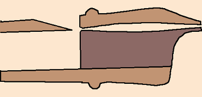
Hmmm, that's a complication to the windway I haven't seen before. Top and bottom sculpting! (Caution, exaggerated image.) We might leave simulating that till Phase II!With very nice diagram, including windway sculpting and nifty chamfers here:
https://www.flute-a-bec.com/gros-plan-chanfreinsgb.html
-
Terry McGee
- Posts: 3335
- Joined: Sun Dec 12, 2004 4:12 pm
- Please enter the next number in sequence: 1
- Location: Malua Bay, on the NSW Nature Coast
- Contact:
Re: Blowing machine
Hmmm, I got to wondering that if this pressure reduction happens at the end of Calibrators, what about at the end of windways in whistles? So I had a quick play.
I plugged the hapless Old Gen whistle head (why me, Lord?) into the Whistle Connector, but with the Upper PTO outlet blocked. And set up 20L/Min flow. And took a tube from the Manometer input to probe around inside the head, coming from the end where the tube should be. The tube is about 1/4" OD, so really a bit big for this - I should use some capillary tube if we wanted to explore more carefully. But I soon found there were two zones:
Running the Manometer tube along the top side of the head (the side where the blade is), pressures start low but build up to around 25mm around the base of the blade. It drops as you enter the window.
Now running the tube along the bottom of the head, it starts low but then goes negative, again peaking around the blade area, but at around -15mm. It's hell in there, folks!
It's probably fair to think of the top side as being in line with the calibrator exit, and the bottom side as being in the backwater. But these backwaters appear not to be dead zones, but negatively pressured.
Now we should put much faith in that quick skirmish, because I can hear that the presence of the relatively thick tube is messing with the acoustics of the head, so probably is doing the same with the pressures. But the general approach might have some relevance at some point in our investigations.
-
david_h
- Posts: 1735
- Joined: Mon Aug 13, 2007 2:04 am
- Please enter the next number in sequence: 1
- Location: Mercia
Re: Blowing machine
Hey - progress! Those experiments clear some of the bafflement.
Up thread I wondered if adding a tube downstream could reduce drag. I found this:
If everything of relevance can be rolled into the K in Tunbourough's model there will be a straight line relationship between Flow and sqrt(Pressure), the slope of which is 'resistance' so not many pressure and flow measurements will be needed. If that is the case (no flow regimes changes etc) then the flow meter issues may be surmountable. With the flow meter upstream of the 'sample' we can correct for the effect of pressure on air volume; it will vary linearly from zero at no flow to a few percent at what we would blow a whistle to. If we are getting a straight line relationship with sqrt(pressure) then it looks like the makers know what they are doing with the strange scale markings. The flowmeter correction for pressure in the image linked several pages back is a different correction. Somewhere on the neutrium.net site I skimmed past what may be the derivation of it. Will have another look but in any case it is also small and linear with flow - it will be a constant error in 'resistance'.
I mainly linked the supercomputer simulation above to contrast with the bench-top stuff. I think the coloured waves are a resonating sound, not a bulk flow. My mention of the what was going on in the windway was in anticipation of something that might come up a few pages on. The resonating volume appears to extend upstream of the jet so could potentially include our mouths. Throat tuning and all that similar stuff?
Neighbours are now away. Will set up in the metaphorical woodshed with whistles, tuner app etc.
Up thread I wondered if adding a tube downstream could reduce drag. I found this:
The calibrator exit is close to being an orifice plate exit. So it think that if Terry made a little 5 degree cone and stuck it on the end of the calibrator (thought experiment only) the 'resistance' and so pressure at the upper PTO would go down. A length of tube isn't that, but maybe it has a similar but lesser effect.https://en.wikipedia.org/wiki/Venturi_effect wrote:
"To avoid undue aerodynamic drag, a Venturi tube typically has an entry cone of 30 degrees and an exit cone of 5 degrees."
<snip>
"Venturi tubes are more expensive to construct than simple orifice plates, and both function on the same basic principle. However, for any given differential pressure, orifice plates cause significantly more permanent energy loss"
If everything of relevance can be rolled into the K in Tunbourough's model there will be a straight line relationship between Flow and sqrt(Pressure), the slope of which is 'resistance' so not many pressure and flow measurements will be needed. If that is the case (no flow regimes changes etc) then the flow meter issues may be surmountable. With the flow meter upstream of the 'sample' we can correct for the effect of pressure on air volume; it will vary linearly from zero at no flow to a few percent at what we would blow a whistle to. If we are getting a straight line relationship with sqrt(pressure) then it looks like the makers know what they are doing with the strange scale markings. The flowmeter correction for pressure in the image linked several pages back is a different correction. Somewhere on the neutrium.net site I skimmed past what may be the derivation of it. Will have another look but in any case it is also small and linear with flow - it will be a constant error in 'resistance'.
I mainly linked the supercomputer simulation above to contrast with the bench-top stuff. I think the coloured waves are a resonating sound, not a bulk flow. My mention of the what was going on in the windway was in anticipation of something that might come up a few pages on. The resonating volume appears to extend upstream of the jet so could potentially include our mouths. Throat tuning and all that similar stuff?
Neighbours are now away. Will set up in the metaphorical woodshed with whistles, tuner app etc.
-
Tunborough
- Posts: 1419
- Joined: Sun Dec 05, 2010 2:59 pm
- antispam: No
- Please enter the next number in sequence: 10
- Location: Southwestern Ontario
Re: Blowing machine
As you point out, the LPTO is in a backwater. When we've got an open pipe downstream of the obstruction, it looks like this, with the right-hand pressure being atmospheric.Terry McGee wrote: ↑Wed Mar 15, 2023 10:27 pm I cut another 40mm piece of 13.3mm tubing, but in this one, I tapped a hole 5mm in from the Calibrator end and screwed in a PTO spigot. So when I push it on to the Calibrator the spigot will commune with the air around the output of the Calibrator. I'll call it "LPTO + 35mm tube".
So start with the end of the Calibrator open to air....
20L gives 73.5 at the upper PTO
Add the LPTO + 35mm tube, upper PTO drops to 66.5mm
Plug Upper PTO and measure at LPTO, -8mm
Diff mode between UPTO and LPTO, 73.5mm

For the calibrator, the difference between the far left pressure and the far right pressure is almost consistent with the Bernoulli pressure drop at the calibrator entrance, and the pressure loss through the calibrator. Without the extension tube, apparently the bottom of the dip lines up with atmospheric pressure. I don't yet have a handle on that additional pressure drop.
-
David Cooper

- Posts: 149
- Joined: Thu Mar 10, 2022 5:24 pm
- antispam: No
- Please enter the next number in sequence: 8
- Tell us something.: I'm about to have a go at making wooden flutes based on a quena - I want to experiment with changing the hole sizes and locations to make one that's more comfortable to play. I just received an auger through the post today, and there are blown-down trees in the garden waiting to be repurposed, so I'll try to make a start on my first prototype at the weekend.
Re: Blowing machine
I find it hard to visualise the set up of the equipment without pictures of each case, but I'm wondering if when you measure the pressure too close to the constriction you're not measuring the pressure of the jet of air coming out of it, but relatively static air at higher pressure around the jet. Add a longer bit of tube before measuring and you have more mixing of the jet with the air around it in the pipe. There are also complications with the apparent pressure being different in different directions, which is how air at lower pressure is able to punch through the hole into air at higher pressure outside, and that's the result of its speed of movement in that direction which can then push up the pressure of the air it's running into, some of which may then be pushed back in the opposite direction around the jet and into your pressure gauge.
-
david_h
- Posts: 1735
- Joined: Mon Aug 13, 2007 2:04 am
- Please enter the next number in sequence: 1
- Location: Mercia
Re: Blowing machine
I have rewritten this post.
How about this summary?
The pressure difference between left and right is due to energy lost to friction. Near the orifice there is an additional pressure loss due to kinetic energy. So the graph will be an irregular descent from the left to right pressures with a dip due to fluid velocity added to it. The graph doesn't show to contribution of each but the fluid will speed up before the entrance and reaches its maximum velocity after the exit at the vena contracta. A page linked earlier is about loss before an entrance and we know from experiment that putting a tube on the exit changes overall losses. That a venturi tube has a conical entry and exit to reduce loss also suggests there is friction loss both sides.
Pressure going below atmospheric shouldn't be the surprise it is (maybe it wasn't to Terry). I now realise the significance of how a https://en.wikipedia.org/wiki/Bernoulli_grip works. My physics textbook mentions that a dry filter paper fitted into a funnel can't be blown out by blowing down the narrow end because atmospheric pressure holds it there against lower pressure between paper and funnel (I guess it's a class experiment).
Presumably some way away from these things there is a slight pressure rise above atmospheric as extra air is appearing locally. I think that it is the momentum of the (lower pressure) air - its kinetic energy - that allows the jet to 'punch its way' into the atmosphere. Pressure is locally variable because the air is flowing (or vice versa).
As we do have flow rate, and may be able to correct for pressure, we can get the velocity at the windway exit. It will be slightly higher a bit beyond that which I guess makes modelling the air reed harder. It looks like the upper PTO should be well back from the windway entrance. I wonder if it is worth making something so that the beak can be pushed through a seal as if it was protruding by a fixed distance into a mouth so that losses are related to the beak rather than beak plus connection to tube. On the low pressure side is there anything better than simply leaving the manometer open to air?
Last edited by david_h on Fri Mar 17, 2023 2:00 am, edited 2 times in total.